


Ford's Roto-Selector: When You Changed the Radio With Your Foot
Ford's Roto-Selector:When You Changed the Radio With Your Foot
Today we have steering-wheel audio controls, touchscreens and voice commands. In 1941, Ford had another solution: Use your foot.
It sounds like an old-car tall tale until you see the period literature - and the installation instructions.
The Roto-Selector Radio Foot Control Switch was designed to let the driver operate the tuning system of a compatible Ford radio without reaching for the dashboard. C&G Ford Parts offers reproduction 11A-18934-A radio foot control switch with wire for applicable 1941-1948 Ford and Mercury passenger-car installations.
And this little switch is considerably more interesting than it looks.
Ford Really Called It the "Roto-Selector"
That name isn't something modern parts sellers dreamed up.
Ford's own 1941 promotional material advertised a new Ford radio with "Roto-Selector Control for fast automatic tuning." Period Lincoln literature also advertised an optional Roto-Selector Radio with foot control and long-distance antenna.
The original installation instructions supplied by C&G are headed "Roto-Selector Radio Foot Control Switch." Those instructions show the switch mounted on the floor between the clutch and brake pedals. Its electrical lead was routed up to the radio receiver and plugged into a socket provided on the receiver itself.
In other words, this wasn't an improvised accessory connected to an ordinary dashboard radio. The foot switch was designed to operate as part of the Roto-Selector radio system.
So What Did the Foot Switch Actually Do?
Here's where terminology matters.
The switch wasn't a modern SEEK control that searched the AM dial looking for the next strong signal. Instead, the Roto-Selector radio used preset stations.
Contemporary Zenith service information describes Roto-Selector tuning as allowing any five desired stations to be selected automatically using either the foot control or the Roto-Selector control on the instrument panel.
So when the driver operated the floor control, he wasn't telling the radio, "Go find me another station." He was telling it, "Move to another station I've already selected."
That's an important difference - and a pretty sophisticated feature for a car radio more than 80 years ago.
There Was More Going On Than a Simple Switch
The original C&G reference material also shows that the installation involved more than the button beneath the driver's shoe.
The accompanying diagram identifies a relay/circuit breaker assembly, wiring to the receiver, a radio suppressor identified as 11A-18827 / 09A-18827, and the associated mounting hardware.
That documentation is particularly useful because it shows us exactly where the reproduction 11A-18934-A fits into the larger system.
The foot switch was the driver's control. The antenna, radio receiver and its Roto-Selector equipment performed the tuning operation.
That's why saying the switch simply "changed the station" doesn't quite tell the whole story.
Why Control a Radio With Your Foot?
Think about manually tuning an automobile radio of the period. You're driving down a two-lane road while turning a tuning knob and watching a dial, trying to land precisely on the station you want.
Preset tuning eliminated much of that fiddling. Moving control of those presets down to the driver's foot meant the radio could be operated without reaching across the instrument panel.
It was an early solution to a problem automakers still work on today: How do you let the driver operate accessories while keeping attention on the road?
Different technology. Same problem.
Radio Was a Big Deal in the 1940s
It's easy to underestimate how important the radio itself was. There was no streaming audio, satellite radio or smartphone in your pocket. Radio brought drivers news, sports, music, weather and entertainment while they traveled.
American broadcasting was expanding rapidly. By June 30, 1948, the Federal Communications Commission reported 2,034 standard AM broadcast stations operating in the United States.
That's a far cry from the handful of choices we sometimes imagine when thinking about an old tube radio.
What Was Reception Like?
Those Ford radios operated in a very different broadcasting environment from today's digital entertainment systems.
AM reception depended on the station's frequency and transmitter power as well as distance, terrain, ground conductivity, interference and atmospheric conditions.
Nighttime could change everything. Medium-wave AM signals can propagate beyond their normal daytime range after sunset because radio energy can return to earth through the ionosphere. That made reception of distant stations possible - sometimes from hundreds of miles away. It could also produce fading and interference.
So the selection of stations available to a driver wasn't necessarily identical at noon and midnight.
Imagine heading down a highway after dark in your Ford. One of your regular stations starts fading as the miles roll by. Instead of leaning toward the dashboard and hunting around the dial, you've already got several stations adjusted into the Roto-Selector. Move your foot. Operate the switch. Bring up another preset.
Now the Roto-Selector starts making a lot more sense.
Five Presets Wasn't Primitive in 1941
Five stations may sound rather limited today. In 1941, it was convenience.
A Ford advertisement from the period specifically promoted the Roto-Selector as "fast automatic tuning." Contemporary Zenith service information confirms selection of five desired stations through the Roto-Selector system.
Instead of repeatedly finding a favorite station manually, the driver could have the desired stations preset.
That's essentially the same basic convenience provided by radio memory buttons for decades afterward - accomplished with vacuum tubes, switches and electromechanical hardware instead of microprocessors.
Did Every 1941-1948 Ford Have One?
No.
This is an important restoration distinction. Ford's own 1941 material describes the radio as an accessory, rather than standard equipment on every car.
An aftermarket replacement-part application covering several years does not prove that every Ford or Mercury radio built during those years originally used exactly the same switch or radio configuration.
C&G therefore lists 11A-18934-A for applicable 1941-1948 Ford and Mercury passenger-car applications. If you're doing a factory-correct restoration, the vehicle year and the radio equipment installed in the car should be considered.
The Kind of Detail That Makes a Restoration Fun
The Roto-Selector is exactly the sort of feature that makes an early Ford interesting.
Everybody notices the steering wheel. Everybody notices the gauges. But somebody eventually looks down at the floor and spots another switch.
"What's that?"
You point toward the radio. "Radio control."
Now you've got a conversation.
And with the original installation instructions available, we don't have to rely on somebody's recollection of how it supposedly worked. We can see where Ford intended the control to be installed, how its lead connected to the receiver, and how the system was laid out.
That's the difference between merely installing an old-car part and understanding the piece of history you're putting back into the car.
11A-18934-A Radio Foot Control Switch With Wire
C&G Ford Parts offers the reproduction 11A-18934-A Radio Foot Control Switch with Wire for applicable 1941-1948 Ford and Mercury passenger-car radio installations.
If you're restoring an original-style radio system and aren't certain whether your receiver uses the Roto-Selector foot control, contact us before ordering.
C&G Ford Parts has been helping enthusiasts keep classic Fords on the road since 1978, and our crew doesn't just sell old-car parts - we own and drive old cars ourselves.
Because sometimes the smallest part under the dashboard has one of the best stories in the whole car.
And yes - in 1941, Ford really did let you operate the radio with your foot.
Sources & Further Reading
• C&G Ford Parts - 11A-18934-A Radio Foot Control Switch
• 1941 Ford promotional literature - Roto-Selector automatic tuning
• 1941 Lincoln-Zephyr brochure - Roto-Selector Radio with foot control
• Zenith service data - Roto-Selector tuning and five-station selection
• Ford News index - period reference to Mercury Roto-Selector foot control
Primary material supplied by C&G Ford Parts: "Roto-Selector Radio Foot Control Switch" installation instructions, including mounting and wiring diagrams.

Steering Wheel Removal Guide
Ford Applications Using D4TZ-3600-A Steering Wheel & D3TZ-13A805-A Horn Pad
Servicing the steering column on classic Ford vehicles often requires removing the steering wheel assembly. When working with steering wheel D4TZ-3600-A and horn pad D3TZ-13A805-A applications, the process is straightforward when approached in the correct sequence and with the proper tool.
This guide outlines the removal procedure based on original shop notes and preserves the mechanical order of operations.
Application Scope
Applies to Ford vehicles equipped with:
D4TZ-3600-A Steering Wheel
D3TZ-13A805-A Horn Pad
TOOL-3600 Steering Wheel Puller
Application may vary by model year or steering column configuration. Always confirm fitment before ordering replacement components.
Original Shop Notes
Remove two screws holding horn pad
Undo wiring clips for horn pad
Loosen steering wheel nut
Attach steering wheel tool
Loosen wheel
Remove tool and nut
Remove wheel
Step-By-Step Technical Interpretation
1. Remove Horn Pad Retaining Screws
The horn pad is secured to the steering wheel by two screws. Removing these fasteners allows access to the internal wiring and steering wheel retaining nut. Use appropriate screwdriver to avoid damaging the screw head.
2. Disconnect Horn Pad Wiring Clips
With the horn pad removed, carefully release the wiring clips connected to the horn contact assembly. These clips must be detached before steering wheel removal to prevent wire strain or terminal damage.
3. Loosen the Steering Wheel Retaining Nut
Loosen the steering wheel nut but do not remove it completely at this stage. Leaving the nut partially threaded helps protect the steering shaft threads during puller use.
4. Install Steering Wheel Puller (TOOL-3600)
Attach the steering wheel puller evenly to the threaded mounting holes in the wheel hub. The puller applies controlled pressure to separate the steering wheel from the tapered steering shaft.
Using a puller prevents damage to the wheel hub and avoids stressing the column bearings or shaft splines.
5. Release the Steering Wheel from the Shaft
Once the puller is properly secured, gradually tighten the tool until the steering wheel breaks free from the taper. After the wheel loosens, remove the puller and fully remove the steering wheel nut.
The steering wheel can then be lifted off the column shaft.
When Steering Wheel Removal Is Necessary
Steering wheel removal is typically required during:
Turn signal switch service
Steering column restoration
Column bearing inspection
Steering wheel replacement
Because the steering wheel is mounted on a tapered shaft, proper tool use is recommended to avoid damage.
Restoration Considerations
On older Ford steering columns, corrosion or age can increase resistance between the wheel hub and shaft taper. Controlled puller pressure is preferable to prying or hammering methods.
Inspect wiring connectors and horn contacts while the assembly is disassembled. Access during wheel removal provides an opportunity to evaluate column components without additional tear down.
Confirm steering column configuration and model year before ordering steering wheels, horn pads, or related steering components.
Explore our full selection of classic Ford steering wheels, horn pads, and steering column components.

Flathead V8 Water Pump and Mount Service Guide
Flathead V8 Water Pump & Mount Service Guide1937–1948 Ford Passenger Car | 1939–1948 Mercury V8
Servicing the cooling system on a 1937–1948 Ford passenger car or 1939–1948 Mercury V8 requires more than just swapping a part. The flathead platform integrates the water pumps, front engine mounts, and cooling hoses in a way that makes access and sequencing important. Whether you’re replacing water pumps, water pump bolts, or addressing motor mounts at the same time, the process benefits from a clear plan.
The parts referenced here include:
78-8501-PR – Water Pumps
78-8501-HK – Water Pump Bolts
78-6038-BDK – Motor Mounts
These components are commonly serviced together on 37–48 Ford and 39–48 Mercury V8 applications due to their physical proximity and shared mounting areas.
Why These Systems Overlap
On these flathead V8 engines, the water pumps mount at the front of the block and are positioned near the front motor mount assembly. In many cases, removing the pumps requires relieving load from the mounts. Aging rubber mounts can sag over time, changing engine position slightly and complicating pump removal or installation. Addressing motor mounts during cooling system service can help maintain proper engine alignment.
Fitment may vary slightly by model year or chassis configuration. Always confirm application for Ford passenger car versus Mercury V8 before ordering parts. Give us a call or email and we will answer your questions!
Basic Removal Sequence
A structured approach reduces stress on hardware and surrounding components:
Drain CoolantBegin by fully draining the cooling system. Open the radiator petcock and, if equipped, block drains to remove as much coolant as possible.
Remove Radiator Hoses (Upper and Lower)Disconnect both hoses from the radiator and water pump outlets. Inspect hose condition during removal.
Loosen Motor Mount BoltsThe front motor mount assembly may need to be loosened to allow slight engine movement. Do not fully remove the mount until the engine is properly supported.
Support the EngineCarefully jack up the engine using a wood block under the oil pan. The wood block helps distribute load. Raise only enough to relieve tension from the mounts.
Remove All Eight Water Pump BoltsEach pump is secured with multiple bolts. Remove all mounting hardware evenly to prevent binding. The water pump bolt kit (78-8501-HK) ensures proper hardware replacement if originals are corroded or worn.
*PRO TIP there is a bolt in each of the lower water pump outlets.
Once the bolts are removed, the water pumps (78-8501-PR) can be removed from the block. Surfaces should be cleaned thoroughly before re-installation.
Motor Mount Considerations
The motor mount kit (78-6038-BDK) supports the engine’s front weight and isolates vibration from the frame. When mounts are deteriorated, engine position may shift slightly. Replacing mounts during water pump service is practical because access is already established and the engine is supported.
Fitment should always be verified for specific Ford passenger car or Mercury V8 applications within the 1937–1948 and 1939–1948 ranges.
Restoration-Focused Approach
Flathead cooling system service is straightforward when handled methodically. These engines were designed for serviceability, but age introduces corrosion, hardware fatigue, and rubber deterioration. Replacing water pumps, water pump bolts, and motor mounts as a coordinated service helps maintain structural alignment and cooling integrity.
Taking the time to follow proper removal steps protects original components and ensures the flathead V8 continues operating as intended.
View our full selection of Flathead V8 Water Pumps and Cooling Components.

1959 PASSENGER/RANCHERO PARK LIGHT HOUSINGS
INTRODUCING A NEW ITEM, THE 1959 PASSENGER AND RANCHERO PARK LIGHT HOUSINGS!
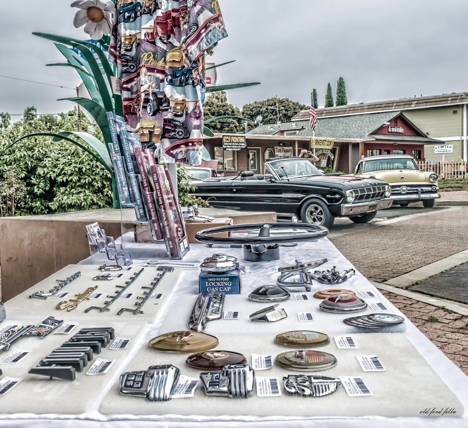
Reviving Nostalgia: Overview of the 1964 Ford Falcon Sprint
The 1964 Ford Falcon Sprint is a classic car that holds a special place in the hearts of many car enthusiasts. This vintage Ford model was known for its sleek design, powerful engine, and affordable price. While it may have been over 50 years since its release, the 1964 Ford Falcon Sprint is still a highly sought-after car for collectors and enthusiasts alike. In this article, we will explore the history of this iconic car and discuss the process of restoring one to its former glory.
The History of the 1964 Ford Falcon Sprint 1964 Ford Falcon Sprint The Ford Falcon was first introduced in 1960 as a compact car designed to compete with other popular models of the time, such as the Chevrolet Corvair and the Plymouth Valiant. In 1963, Ford released the Falcon Sprint in hardtop and convertible, a sportier version of the original Falcon. The Sprint featured a 260 cid V8 engine, bucket seats, and a floor-mounted shifter (when equipped with the optional 4 speed), making it a popular choice among car enthusiasts. The Falcon Sprint hardtop was also used in various racing events, solidifying its reputation as a high-performance vehicle.
If you're looking to restore a 1964 Ford Falcon Sprint, the first step is to find one for sale. While it may be challenging to find one in good condition, there are still some available for purchase. You can search online for classic car dealerships or browse through online marketplaces such as eBay or Craigslist. It's essential to thoroughly inspect the car before making a purchase, as it may require significant restoration work. Restoring a vintage car like the 1964 Ford Falcon Sprint requires a lot of time, effort, and money. It's crucial to have a clear plan and budget in place before starting the restoration process. The first step is to assess the condition of the car and determine which parts need to be replaced or repaired. It's essential to use original or high-quality reproduction parts to maintain the authenticity and value of the car.
Once you have successfully restored your 1964 Ford Falcon Sprint, it's crucial to maintain it properly to preserve its value and performance. Regular maintenance, such as oil changes, tune-ups, and inspections, is essential to keep the car running smoothly. It's also essential to store the car in a dry, climate-controlled environment to prevent rust and other damage.
Owning a 1964 Ford Falcon Sprint is more than just having a classic car; it's about reviving nostalgia and preserving a piece of history. Restoring this iconic car is a labor of love that requires dedication and passion. But the end result is a beautiful, high-performance vehicle that will turn heads and bring joy to its owner.
Are you a fan of the 1964 Ford Falcon Sprint? Have you restored one yourself? Share your thoughts and experiences in the comments below.

INSTALLING A CLASSIC FORD DISTRIBUTOR INTO OLD FORD TRUCKS AND CARS
INSTALLING A CLASSIC FORD DISTRIBUTOR
1932-1941 Old Ford Trucks, 1932-1941 Ford Passenger Cars and 1939-1941 Mercury Cars with original V8 distributor:
1. Check inner caps one at a time to make sure they fit distributor housing, sand them if needed. Also check to make sure once installed rotor does not hit the inner cap. After fitting inner caps put inner and outer caps together with the spark plug wires and set aside.
2. Mount coil to distributor making sure coil brush makes contact with rotor and copper contact is not bent.
3. Make sure the mounting surface is clean and there is nothing in the camshaft slot where the distributor mounts. Check to make sure mounting bolt threads are clean and free of dirt, set bolts on top of engine for easy reach.
4. Time to mount the distributor. Put gasket on base of distributor, you can put a small amount of sealant on the gasket. Place distributor on to timing cover using fingers to turn rotor to make sure distributor is correctly seated in the camshaft. The distributor will mount flat to the timing cover when correctly installed. If the distributor is not seated correctly you can crack the distributor case when you tighten the bolts. Now you can put the three mounting bolts in and tighten. Do not over tighten(snug).
5. Install inner/outer caps to the distributor and pop the bail over to hold in place.
6. Install vacuum line to distributor.
1941-47 (6 Cylinder “G” Engine) Old Ford Trucks and Passenger Cars, 1942-1947 Old Ford Trucks and 1942-1948 Passenger Cars/Mercury Cars (V8):
1. Make sure the mounting surface is clean and there is nothing in the camshaft slot where the distributor mounts. Check to make sure mounting bolt threads are clean and free of dirt, set bolts on top of engine for easy reach.
2. Place the rotor on distributor and mount distributor cap and turn rotor slowly to make sure the rotor does not hit the inner cap. If rotor hits cap lightly file end of rotor till it clears. Remove distributor cap and set aside. Leave rotor on distributor.
3. Time to mount the distributor. Put gasket on base of distributor, you can put a small amount of sealant on the gasket, be sure not to get sealant on vacuum rubber grommet. Place distributor on to timing cover using fingers to turn rotor to make sure distributor is correctly seated in the camshaft. The distributor will mount flat to the timing cover when correctly installed. If the distributor is not seated correctly you can crack the distributor case when you tighten the bolts. Now you can put the two mounting bolts in and tighten. Do not over tighten(snug).
4. Install distributor cap and pop clips on for 42 crab cap. If you have a 46-48 with the inner and outer cap you will have to install plug wires into cap first before installing caps on distributor.
YOUR CLASSIC FORD PARTS STORE
YOUR CLASSIC FORD PARTS STORE
If you own a classic Ford, you’re used to dependability. You go out, you start the vehicle, and it runs. That’s the way it should be. After all, when it’s an older Ford, it has longevity built right into it.
Sometimes, though, things will take a toll on the best ride you’ve ever owned. Could be the weather - or a little ding or two that happens when someone isn’t paying attention and they run into you. Whatever the reason, if you’ve got something on your list that you need for your old Ford, you can find it at a C&G Ford Parts. You’ll find thousands upon thousands of parts that can get your Ford in the best shape, even if you own one from the late 1970's.
That’s sure to give you peace of mind right there. Say you’ve got a 1979 Ford F150 pickup. The jet-black custom paint on it just glints in the sunlight. Your truck is the envy of the neighborhood and everywhere else that you take it. You worked hard for that truck and you deserve to show it off. Taking a friend out for a round or two of golf, you park the truck in the lot carefully away from other cars. But you know how it goes. There always has to be someone who parks right up on you. Only this time, they broke your driver’s side mirror up pretty good and took off without having the decency of letting anyone know. When you do a thorough examination, you see that the door is fine, but the mirror can’t be repaired - the damage is too bad. It’s got to be replaced. Besides making you mad, you’re now faced with the task of figuring out where you’re going to go to get one like it.
No worries, because you can get the part you need right at a classic Ford parts store, C&G Ford Parts to be exact. Places that have the stock you’re looking for can easily cover getting you that mirror in no time. Best of all, getting that replacement mirror in an exact match for your truck isn’t going to cost you every penny you’ve got in the bank. At C&G Ford parts, not only will you find what you need when you need it, but you’ll find it for a reasonable price as well. You can’t always prevent bad drivers from doing foolish things and ending up damaging your Ford. But you can rest assured knowing that a C&G Ford parts has got you covered. So take that truck out for a spin any time. They’ll be waiting on you when you need them.

Old Ford Drum Brake History and Tutorial
Old Ford drum brake history and tutorial
Pre 1967 old Ford cars and old Ford trucks used a drum brake system. In these systems, pressure applied to the brake pedal is transmitted to the master cylinder, which in turn disperses the energy ultimately to the brakes in each wheel. The master cylinder uses the brake fluid to move the wheel cylinders, which in turn moves the brake shoes in the drum.
There is a front and back brake shoe, the rear one for stopping a vehicle in drive and the forward one for stopping a vehicle in reverse. When either shoe is pressed against the anchor pin, the brakes are engaged, and the vehicle comes to a stop. The brake pads form the shoes to the anchor pin so there is no slipping. The padding on the rear brake shoe is typically longer and sometimes made of a different material to allow the shoes to wear at a similar rate, since the rear shoe sees much more use.
The brake shoes are secured in the drum with both hardware and return springs, which must meet ideal sizing and tension specifications for your make and model for top brake performance. These parts should be replaced any time you work on the brakes in order to counteract wear and tear that can lead to longer stopping times.
Stock brake line hoses will have a rubber lining, while aftermarket hoses are available in a stainless braided wrap to preserve the hose. Whichever type you get, make sure the hoses are the correct thread size and length for your year and model and meet DOT safety standards. The rear wheel drum brakes will also contain the parking brake mechanism and will have a cable to the parking brake.
Brake pipe must be double flared and use flared nuts. It can be purchased with the flaring already completed or you can cut your own and flare it yourself, but it should meet or exceed DOT safety standards.
Hydraulic brakes will fail if there is a weak point in the system, so make sure all your hose and fittings are SAE rated and correctly installed. If you are unsure after installation, test the brakes at low speed in a safe area, such as your driveway or an empty parking lot before taking the vehicle on the road.
Starting in 1967 all old fords have a dual master cylinder. This part separates the wheel hydraulics of the front and rear of the car, so a failure in one will not cause a failure in the other. In vehicles without this feature, a leak anywhere in the brake line will cause the entire brake system to fail. With a dual master cylinder, a leak in the front brake system will not affect the rear and vice versa. This is standard in vehicles made after '67, but it's a good safety upgrade for older classic Fords as well.
Many classic Ford owners choose to upgrade their front brake system to disc brakes, or the complete system. Drum brakes can overheat and fail in high braking conditions, such as rapid stops at high speeds or driving downhill on mountainous roads. Disc brakes are open and exposed to the outside air, which prevents overheating and brake failure. While this upgrade is not strictly necessary, it's a good idea if you frequently drive in hilly or mountainous areas.
Original Ford brake shoes used asbestos in the brake pads. If you are working on a vehicle with its original brake shoes or if you are uncertain if they are original, wear a respirator rated for asbestos while working and wet the brake pads before opening the drum to prevent the asbestos from becoming air born. When cleaning dust from drum brakes, use a dense filtration system to trap the asbestos and dispose of it properly.
You can resurface a drum with minor surface issues, but make sure it stays within factory limits for your year and model. Worn or thin drums can break apart or crack and cause brake failure. If you see excessive wear and tear, replace the drum.
If you are replacing a leaking wheel cylinder, it's a good idea to do them all at once, including the master cylinder. If you have had problems with one, you will soon have problems with the rest. In addition, you won't need to remember which cylinder was replaced when for future maintenance if they were all replaced at once.
You can use a vacuum bleeder to remove old brake fluid and contaminants. Once you remove the old fluid you can use denatured alcohol followed by air to purge the lines. Vacuum each cylinder, including the master cylinder, and replace the old fluid with new, DOT 3 or 4 fluids. When changing fluid, change the rubber hoses and seals. If you have a combination disc and drum system, only use DOT 4 fluid. To ensure a complete cleaning, vacuum some of the new fluid through as well do catch any missed contaminants.
When working on or near the brake line, make sure no petroleum-based liquid, such as gasoline, oil, or mineral oil, encounters the hosing. These oils can break down the rubber and cause hoses to start leaking. Make sure to wash your hands thoroughly before and during working on the brakes system to prevent this, especially if you have been working on other parts of the vehicle.
When working on your brakes, make sure to follow safety precautions, use safety rated parts, and check over your work carefully. Drum brakes are a very important part of the machinery, and due to the hydraulic system, can easily lose stopping power or fail if something is wrong, especially without a dual master cylinder. Whether you're doing regular maintenance or upgrading the whole system, working carefully will ensure a successful job for your vehicle.


